Difference between revisions of "I2C"
From ArmadeusWiki
| Line 1: | Line 1: | ||
This page will summarize the informations to use the I2C bus on our boards. | This page will summarize the informations to use the I2C bus on our boards. | ||
| − | + | ==Tested I2C chips== | |
| + | * RTC | ||
| − | + | ==APF9328 I2C bus logic level adaptation (if necessary)== | |
| − | PCA9306 from NXP ( | + | On the APF9328 the I2C bus has a 3,3V logic level so '''if you want to use 5V I2C devices you have to add a level converter''', for example a PCA9306 from NXP (ex Philips): |
* Connect pin 1 to the local GND | * Connect pin 1 to the local GND | ||
* Connect pin 2 to the local 3.3V | * Connect pin 2 to the local 3.3V | ||
| Line 13: | Line 14: | ||
* Connect a pullup of 1.7K to the 5V SDA line (pin 5) | * Connect a pullup of 1.7K to the 5V SDA line (pin 5) | ||
| − | For more details, take a look at the | + | For more details, take a look at the [http://www.nxp.com/acrobat_download/datasheets/PCA9306_2.pdf PCA9306 datasheet]. |
| − | + | This chip is the one that will be used on the DevFull board. | |
| − | + | [[Image:I2C_5V.png]] | |
| − | + | ||
==Links== | ==Links== | ||
* [http://mbouget.club.fr/i2c-faq.html Vincent Himpe I2C FAQ mirror] | * [http://mbouget.club.fr/i2c-faq.html Vincent Himpe I2C FAQ mirror] | ||
Revision as of 13:45, 14 July 2007
This page will summarize the informations to use the I2C bus on our boards.
Tested I2C chips
- RTC
APF9328 I2C bus logic level adaptation (if necessary)
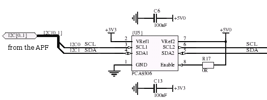
On the APF9328 the I2C bus has a 3,3V logic level so if you want to use 5V I2C devices you have to add a level converter, for example a PCA9306 from NXP (ex Philips):
- Connect pin 1 to the local GND
- Connect pin 2 to the local 3.3V
- Connect pin 3 to the SCL output of the APF
- Connect pin 4 to the SDA input/ouput of the APF
- Connect pin 7 and 8 together and the add a 200K resistor in parallel to a 100nF capacitor to GND
- Connect a pullup of 1.7K to the 5V SCL line (pin 6)
- Connect a pullup of 1.7K to the 5V SDA line (pin 5)
For more details, take a look at the PCA9306 datasheet.
This chip is the one that will be used on the DevFull board.
