Difference between revisions of "LQ043 Adapt"
| Line 1: | Line 1: | ||
| − | This adaptor board allows you to connect a [http://document.sharpsma.com/files/LQ043T3DX02_SP_122805.pdf Sharp's LQ043 LCD] to your | + | This adaptor board allows you to connect a [http://document.sharpsma.com/files/LQ043T3DX02_SP_122805.pdf Sharp's LQ043 LCD] to your docking board. |
| + | |||
The description, the datasheet and the schematics of this adaptor board [http://www.armadeus.com/english/products-peripherals-lq043_adapt.html can be found here.] | The description, the datasheet and the schematics of this adaptor board [http://www.armadeus.com/english/products-peripherals-lq043_adapt.html can be found here.] | ||
| Line 7: | Line 8: | ||
{| border="1" cellpadding="5" cellspacing="0" summary="Connection table" | {| border="1" cellpadding="5" cellspacing="0" summary="Connection table" | ||
|- style="background:#efefef;" | |- style="background:#efefef;" | ||
| − | ! ''' ''' || '''APF27Dev''' || '''APF9328DevFull''' || '''APF9328DevLightV1''' || ''' APF9328DevLightV2''' | + | ! ''' ''' || '''APF27Dev''' || '''OPOS6ULDev''' || '''APF9328DevFull''' || '''APF9328DevLightV1''' || ''' APF9328DevLightV2''' |
|---------------- | |---------------- | ||
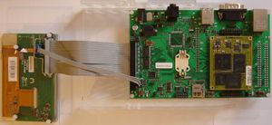
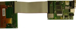
| − | | '''TFT usage''' || flat cable (1) connected between J10 of the APF27Dev and X5 of the LCD_Adapt [[Image:LQ043_Adapt_to_APF27Dev.jpg|thumb|Connection between APF27Dev and LQ043_Adapt]] || flat cable (1) connected between X12 of the DevFull and X5 of the LCD_Adapt || On the Devlight V1, the LCD port is not prerouted. This means that you have to solder several wire between the vias corresponding to the LCD signals and a free place on the board where you can add a 2x15pins header. Take a look at the Devlight datasheet. You will find a table representing the bottom side of the board. On the board (bottom), you will see a silkscreen indicating the names of each vias. In the LQ043_Adapt datasheet, you will find the pin description of the 2x15 pins connector. Connect (1 to 1) the signals of the LQ043_adapt to the ones of the Devlight.The flat cable (1) is although required || flat cable(1) connected between X5 of the LCD_Adapt and LCD connector of the DevLight [[Image:LQ043_Adapt_to_DevLightV2.jpg|thumb|Connection between DevLight V2 and LQ043]] | + | | '''TFT usage''' || flat cable (1) connected between J10 of the APF27Dev and X5 of the LCD_Adapt [[Image:LQ043_Adapt_to_APF27Dev.jpg|thumb|Connection between APF27Dev and LQ043_Adapt]] || flat cable (1) connected between TFT_J23 connector of the Dev and X5 of the LCD_Adapt|| flat cable (1) connected between X12 of the DevFull and X5 of the LCD_Adapt || On the Devlight V1, the LCD port is not prerouted. This means that you have to solder several wire between the vias corresponding to the LCD signals and a free place on the board where you can add a 2x15pins header. Take a look at the Devlight datasheet. You will find a table representing the bottom side of the board. On the board (bottom), you will see a silkscreen indicating the names of each vias. In the LQ043_Adapt datasheet, you will find the pin description of the 2x15 pins connector. Connect (1 to 1) the signals of the LQ043_adapt to the ones of the Devlight.The flat cable (1) is although required || flat cable(1) connected between X5 of the LCD_Adapt and LCD connector of the DevLight [[Image:LQ043_Adapt_to_DevLightV2.jpg|thumb|Connection between DevLight V2 and LQ043]] |
|---------------- | |---------------- | ||
| − | | '''Touchscreen usage''' || 4 wires cable (2) connected between X2 of the LCD_Adapt and J14 of the APF27Dev || 4 wires cable (2) connected between X2 of the LCD_Adapt and X32 of the DevFull || colspan="2" align="center" | For those who do not have the APF9328Devfull and would like to use a touch panel, a reserved space has been foreseen on the LQ043_adapt board to solder the [[TSC2102]] (U3) and a small regulator (LM317/U4) . This avoids developping or buying a dedicated PCB.In that case one more connection is required: | + | | '''Touchscreen usage''' || 4 wires cable (2) connected between X2 of the LCD_Adapt and J14 of the APF27Dev || Not tested || 4 wires cable (2) connected between X2 of the LCD_Adapt and X32 of the DevFull || colspan="2" align="center" | For those who do not have the APF9328Devfull and would like to use a touch panel, a reserved space has been foreseen on the LQ043_adapt board to solder the [[TSC2102]] (U3) and a small regulator (LM317/U4) . This avoids developping or buying a dedicated PCB.In that case one more connection is required: |
* connect LQ043 X7 pin 2 (SSI_B5) with DevLight SSI1_TxDAT. No 4 wire cable is required. The TSC2102IDA and the LM317LIDR can be purchased or shipped as samples. Take a look at here: http://focus.ti.com/docs/prod/folders/print/tsc2102.html and http://focus.ti.com/docs/prod/folders/print/lm317l.html | * connect LQ043 X7 pin 2 (SSI_B5) with DevLight SSI1_TxDAT. No 4 wire cable is required. The TSC2102IDA and the LM317LIDR can be purchased or shipped as samples. Take a look at here: http://focus.ti.com/docs/prod/folders/print/tsc2102.html and http://focus.ti.com/docs/prod/folders/print/lm317l.html | ||
|- | |- | ||
| Line 24: | Line 25: | ||
==(2) 4 wires cable == | ==(2) 4 wires cable == | ||
It is a simple one to one 4 wire cables (2.54mm single row headers on both boards: LQ043_adapt and Devfull) | It is a simple one to one 4 wire cables (2.54mm single row headers on both boards: LQ043_adapt and Devfull) | ||
| + | |||
| + | ==OPOS6ULDev== | ||
| + | Default video PLL cannot generate 8,69MHz pixel clock needed by the LCD (too low), so you need to tweek CCM register a little before booting Linux: | ||
| + | <pre class="apf"> | ||
| + | BIOS> mw.l 0x020c4038 0x0002f150 | ||
| + | </pre> | ||
== Ressources == | == Ressources == | ||
Latest revision as of 17:50, 13 March 2017
This adaptor board allows you to connect a Sharp's LQ043 LCD to your docking board.
The description, the datasheet and the schematics of this adaptor board can be found here.
The following table summarizes the possibilities to connect the LQ043 and the Touchscreen to your development board:
| APF27Dev | OPOS6ULDev | APF9328DevFull | APF9328DevLightV1 | APF9328DevLightV2 | |
|---|---|---|---|---|---|
| TFT usage | flat cable (1) connected between J10 of the APF27Dev and X5 of the LCD_Adapt | flat cable (1) connected between TFT_J23 connector of the Dev and X5 of the LCD_Adapt | flat cable (1) connected between X12 of the DevFull and X5 of the LCD_Adapt | On the Devlight V1, the LCD port is not prerouted. This means that you have to solder several wire between the vias corresponding to the LCD signals and a free place on the board where you can add a 2x15pins header. Take a look at the Devlight datasheet. You will find a table representing the bottom side of the board. On the board (bottom), you will see a silkscreen indicating the names of each vias. In the LQ043_Adapt datasheet, you will find the pin description of the 2x15 pins connector. Connect (1 to 1) the signals of the LQ043_adapt to the ones of the Devlight.The flat cable (1) is although required | flat cable(1) connected between X5 of the LCD_Adapt and LCD connector of the DevLight |
| Touchscreen usage | 4 wires cable (2) connected between X2 of the LCD_Adapt and J14 of the APF27Dev | Not tested | 4 wires cable (2) connected between X2 of the LCD_Adapt and X32 of the DevFull | For those who do not have the APF9328Devfull and would like to use a touch panel, a reserved space has been foreseen on the LQ043_adapt board to solder the TSC2102 (U3) and a small regulator (LM317/U4) . This avoids developping or buying a dedicated PCB.In that case one more connection is required:
| |
(1) Flat cable
A simple flat cable (PC like) can be used to connect the LQ043_Adapt to the APF27Dev/APF9328DevFull. If you do not have one, a ready to use cable can be found here.
Align the pins 1 (square via) on both boards together.
Do not use long cables.
(2) 4 wires cable
It is a simple one to one 4 wire cables (2.54mm single row headers on both boards: LQ043_adapt and Devfull)
OPOS6ULDev
Default video PLL cannot generate 8,69MHz pixel clock needed by the LCD (too low), so you need to tweek CCM register a little before booting Linux:
BIOS> mw.l 0x020c4038 0x0002f150

