Difference between revisions of "Led sensor"
From ArmadeusWiki
(→How does it work ?) |
|||
| Line 1: | Line 1: | ||
| − | |||
| − | |||
| − | |||
| − | |||
= How does it work ? = | = How does it work ? = | ||
| Line 23: | Line 19: | ||
When led is charged, fsm disconnect ''cathode'' and count until the ''value'' | When led is charged, fsm disconnect ''cathode'' and count until the ''value'' | ||
| − | reach 0. The result of count is available on 16bits read register. | + | reach 0. The result of count is available on 16bits read register (named |
| + | counter). Counter can be convert in time with formula : | ||
| + | divisor x clock_period x counter = led_disharge_period | ||
| + | By default, divisor is equal to 10. It's possible to change the divisor writing on the same register (named divisor). | ||
[[Image:ledtouchgraph.png|500px|center]] | [[Image:ledtouchgraph.png|500px|center]] | ||
| − | |||
| − | |||
| − | |||
| − | |||
| − | |||
| − | |||
| − | |||
| − | |||
| − | |||
| − | |||
| − | |||
| − | |||
Revision as of 21:29, 25 September 2008
How does it work ?
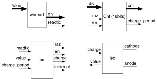
Ledsensor ip formed by by four entities :
- cnt : like «counter» this entity provide counter to measure ledcapacitor discharge, it also provide charge period timing.
- led : This entity is used to drive the led. It has four signal, one to load capacitor «charge», one to read led value and two others to branch led (cathode and anode).
- wbread : This entity is Wishbone 16-data bits bus manager.
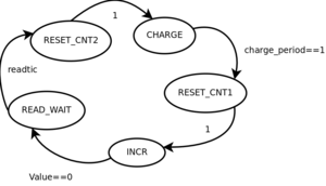
- fsm : This is the main component of the IP, this state machine drive the component. The working of the fsm is describe below :
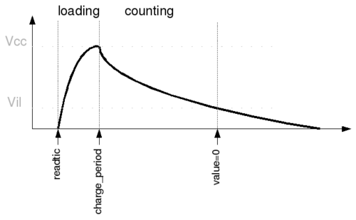
On read from wishbone16, the fsm will reset the counter and load the led during a charge_period.
When led is charged, fsm disconnect cathode and count until the value reach 0. The result of count is available on 16bits read register (named counter). Counter can be convert in time with formula :
divisor x clock_period x counter = led_disharge_period
By default, divisor is equal to 10. It's possible to change the divisor writing on the same register (named divisor).


