Difference between revisions of "OV9655"
From ArmadeusWiki
(→Links) |
|||
| Line 20: | Line 20: | ||
{|border=0 summary="" | {|border=0 summary="" | ||
|--- | |--- | ||
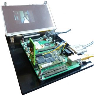
| − | [[Image: | + | [[Image:OV9655_adapt_plugged_on_APF27Dev.jpg|thumb|320px|APF27Dev with OV9655 and LCD]] |
|| | || | ||
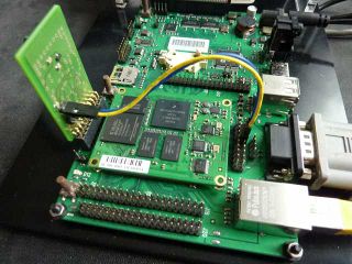
| − | [[Image: | + | [[Image:OV9655_adapt_I2C.jpg|thumb|320px|OV9655_adapt montage (I2C cable: Green on J8 pin 8 and Blue on J8 pin 10)]] |
|--- | |--- | ||
|} | |} | ||
Revision as of 17:33, 15 September 2011
Page under construction...
 Informations on this page are not guaranteed !!
OV9655 is an Omnivision 1,3 Mpixels sensor that can be found in the following commercial camera modules:
- OV09655-FSL
- do you know others ?
Contents
Connecting the OV0955-FSL module to the APF27
- Datasheet of the OV0955 module are available here. They only detail the hardware interface.
- Omnivision sensors are easily available but when it comes to obtain the datasheet of the sensor it becomes harder. Even if you find some datasheet, the informations inside must be read with caution: some are erronous. So here is one of those.
- This modules needs this Molex connector to be plugged in: http://radiospares-fr.rs-online.com/web/5426700.html.
Description
- CSI port (8 bits data + 4 bits control signals) is used to transmit images. (10 bits mode not usable on i.MX). These signals are available on the APF27Dev J9 connector (2,5V logic).
- I2C bus is used to configure the sensor. This bus is available on the APF27Dev J8 connector.
- Sensor core power supply (1,8V) is derived from 2,8V of J9.
Adaptation board
- (Preliminary) Schematics and layouts (Eagle) of an APF27 adaptation board are available here: ....

