Difference between revisions of "Measuring speed and distance"
(→Test) |
|||
| (3 intermediate revisions by the same user not shown) | |||
| Line 1: | Line 1: | ||
{{Under_Construction}} | {{Under_Construction}} | ||
| − | On this page you will find informations to measure speed and distance of a vehicle, with an [[ | + | On this page you will find informations to measure speed and distance of a vehicle, with an [[APF27Dev]] or an [[APF51Dev]] (coming soon). |
==Principle== | ==Principle== | ||
| − | On one wheel of your vehicle, you will have a system with some holes that will generates a square signal. Each pulse will correspond to one or more turn, depending on the precision you need. == a | + | On one wheel of your vehicle, you will have a system with some holes that will generates a square signal. Each pulse will correspond to one or more turn, depending on the precision you need. == a kind of tachometer. |
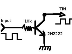
| − | You have to adapt the signal level to 0-2,8V and limit the overshots. <br> | + | You have to adapt the signal level to 0-2,8V (on APF27) or 0-3,3V (on APF51) and limit the overshots. <br> |
| − | Then, you will be able to inject on the TIN input of the APF27. This is only possible if you have an APF27Dev | + | Then, you will be able to inject the signal on the TIN input of the APF27 or on the FPGA of the APF51. This is only possible if you have an APF27Dev and '''don't plan to use the HDMI chip'''. |
The TIN input is internally linked in the i.MX27 to some counters that we will configure and use to count the signal pulses. | The TIN input is internally linked in the i.MX27 to some counters that we will configure and use to count the signal pulses. | ||
| + | For the APF51 a counter will be implemented in the FPGA. | ||
==Montage== | ==Montage== | ||
| + | {|border=0 summary="Photos" | ||
| + | |---------------- | ||
| + | [[Image:Montage_with_ad9889.png|thumb|left|Montage to adapt input signal voltage (APF27Dev only)]] | ||
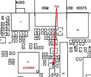
| + | [[Image:TIN_on_R24.jpeg|thumb|center|TIN on APF27Dev (left side of R24 resistor)]] | ||
| + | |} | ||
| + | |||
===Test=== | ===Test=== | ||
* Load driver that will allocate GPT2 timer: | * Load driver that will allocate GPT2 timer: | ||
| Line 28: | Line 35: | ||
==Links== | ==Links== | ||
| + | * http://www.ecomotionteam.org | ||
Latest revision as of 20:48, 18 December 2012
Page under construction...
 Informations on this page are not guaranteed !!
On this page you will find informations to measure speed and distance of a vehicle, with an APF27Dev or an APF51Dev (coming soon).
Contents
Principle
On one wheel of your vehicle, you will have a system with some holes that will generates a square signal. Each pulse will correspond to one or more turn, depending on the precision you need. == a kind of tachometer.
You have to adapt the signal level to 0-2,8V (on APF27) or 0-3,3V (on APF51) and limit the overshots.
Then, you will be able to inject the signal on the TIN input of the APF27 or on the FPGA of the APF51. This is only possible if you have an APF27Dev and don't plan to use the HDMI chip.
The TIN input is internally linked in the i.MX27 to some counters that we will configure and use to count the signal pulses.
For the APF51 a counter will be implemented in the FPGA.
Montage
Test
- Load driver that will allocate GPT2 timer:
# insmod gpt2_plat.ko
- Configure GPT2 for taking TIN as input and activates it:
# imxregs TCTL2 0x00000007
- Check that counter is increasing:
# imxregs TCN2

GPT Counter Register 2
TCN2                     0x00000022  -> 00000000 00000000 00000000 00100010

