HMS Demo
From ArmadeusWiki
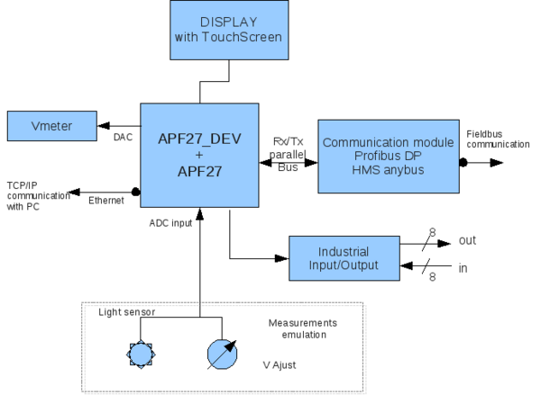
HMS demo board is an electronic development board that demonstrates industrial capabilities of the APF27 ARMadeus board.
This article will describe the structure of the board.
Introduction
Hardware structure
This board includes :
- An Anybus[1] CompactCom adaptator from HMS.
- 8 industrial inputs using SN65HVS882 chip
- 8 industrial outputs with simple shift register
- a LCD screen
- Voltage needles
- Light sensor
- Potentiometer button
- and all APF27Dev capabilities
FPGA structure
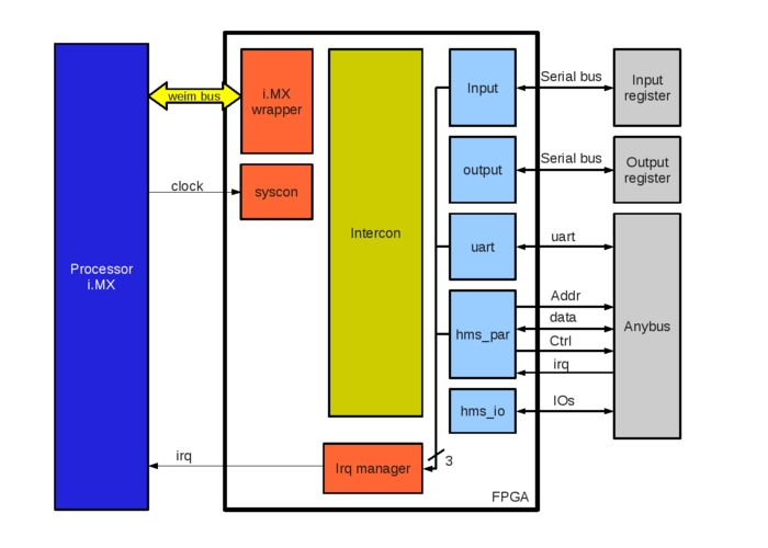
The structure of the FPGA is represented bellow. All modules are connected on i.MX wrapper with the wishbone bus (16 bits data), the intercon is used to decode addresses.
Components are included in FPGA using POD to ease integration :
- input : Read input value using a serial bus like SPI. This component can generate an interrupt on input change.
- output: Write output value using a serial bus like SPI.
- uart : Anybus CompactCom can be driven using a simple uart TTL bus.
- hms_par: For more complex design, Anybus CompactCom can use a «parallel bus» like memory bus.
- hms_io : Anybus has some IO for status and configuration, this component is used to configure it.
Software structure
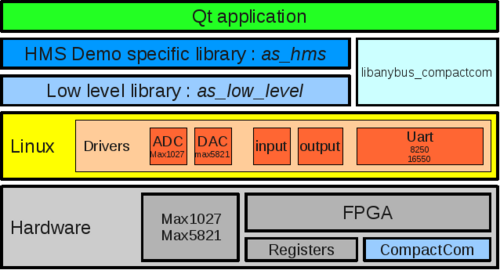
Demo kit software structure is composed of some layers as described in figure 3 :
- Linux BSP : Linux distribution used in kit is the ARMadeus sourceforge tree. Some specific modules must be added :
- ADC max1027 : driver for max1027 analog to digital converter.
- DAC max5821 : driver for max5821 digital to analog converter.
- input, output : driver for fpga specific input/output.
- uart : driver for uart used to drive HMS module.
- as_low_level : low level library used to drive max1027 and max5821
- as_hms : high level library used to drive all devices on board.
- Qt application : graphical application for human interface.


