Difference between revisions of "ADC max1027"
m (→Links) |
(sysfs interface) |
||
| Line 44: | Line 44: | ||
==="Slow" interface (for temperature or battery level measurements)=== | ==="Slow" interface (for temperature or battery level measurements)=== | ||
Several interfaces in ''/sys/bus/spi/devices/spi...'' are created in order to: | Several interfaces in ''/sys/bus/spi/devices/spi...'' are created in order to: | ||
| − | * read the 8 inputs ( | + | * read the 8 analog inputs values: ''inx_input'' (in mV) |
| − | * read the temperature ( | + | * read the temperature: ''temp1_input'' (in m°C) |
| − | * modify the | + | * modify the max1027 registers: ''conversion, setup & averaging'' |
An input can be read like that: | An input can be read like that: | ||
| Line 54: | Line 54: | ||
# cat /sys/bus/spi/devices/spi1.0/temp1_input | # cat /sys/bus/spi/devices/spi1.0/temp1_input | ||
| − | '''These values are only | + | '''These values are only updated each time you launch a conversion and are only dedicated to measure slow evolving greats.''' |
==="Fast" interface (frequencies > 10Hz)=== | ==="Fast" interface (frequencies > 10Hz)=== | ||
Revision as of 11:10, 12 September 2008
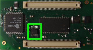
Instructions to install and use the MAX1027 ADC. This device is an option of the APF9328 boards. To know if you have one on your board, take a look at the connectors side:

If you don't have one and are a good electronician, you can order a sample at Maxim's website and solder it directly on your board (footprint is available).
Contents
Introduction
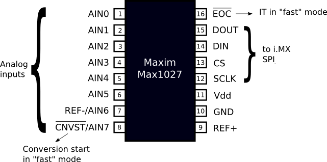
The Max1027 is an 8 channels 10 bits A/D converter with an integrated temperature sensor.
Hardware
The 8 inputs voltage range is [0 - 3,3V]. Don't try to put higher voltage on ADC inputs !!
The i.MXL SPI_1 interface is used to communicate with the device.

If you want to use MAX1027 in "fast" mode (ie measure signals with frequencies > 10 Hz) then you will have to connect #EOC pin (End Of Conversion) to an i.MXL GPIO, configured as Interrupt (see apf9328.c for more details).
Driver
For the Linux kernel, the Max1027 is considered as a Hardware Monitoring device. For the moment only a low speed interface (/sys) is available: the eight channels and the temperature are updated every 10ms.
Installation
- From the top directory:
$ make linux-menuconfig
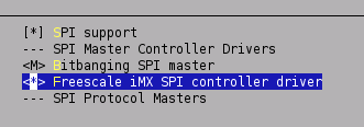
- Then select in Device Drivers->SPI support->Freescale iMX SPI controler driver (builtin not module !!)
- Then select in Device Drivers->Hardware Monitoring Support->MAX1027 sensor chip (Module)
- Once the new config saved, rebuild your image
$ make
and copy hwmon.ko and max1027.ko driver to your target or reflash your rootfs.
- On the target, the driver can be started like this:
# insmod /lib/modules/drivers/hwmon/hwmon.ko
# insmod /lib/modules/drivers/hwmon/max1027.ko
- or like this if you reflashed your rootfs:
# modprobe max1027
Usage
"Slow" interface (for temperature or battery level measurements)
Several interfaces in /sys/bus/spi/devices/spi... are created in order to:
- read the 8 analog inputs values: inx_input (in mV)
- read the temperature: temp1_input (in m°C)
- modify the max1027 registers: conversion, setup & averaging
An input can be read like that:
# cat /sys/bus/spi/devices/spi1.0/in0_input
The temperature can be read like that:
# cat /sys/bus/spi/devices/spi1.0/temp1_input
These values are only updated each time you launch a conversion and are only dedicated to measure slow evolving greats.
"Fast" interface (frequencies > 10Hz)
In that case you can use /dev interface (using blocking read to wait end of conversion). To create /dev nodes you can use the loadmax.sh script. As driver MAJOR number is dynamically allocated, you may need to update /dev depending on the drivers loaded on you system.
- repeatedly read value of input 0 (variable sampling rate = depends on system load):
# cat /dev/max1027/AIN0
- read input 0 once:
# time dd if=/dev/max1027/AIN0 bs=2 count=1 > tmp.bin
# hexdump tmp.bin
Chip registers configuration
Independent of the mode, /sys interfaces allow direct access to the corresponding register in the MAX1027:
# let conv=0xb9; echo $conv > /sys/bus/spi/devices/spi1.0/conversion
You can also get current values of conversion, averaging and setup register with:
# cat /sys/bus/spi/devices/spi1.0/setup
0x62
For more details on how to use these registers, take a look at the datasheet.
Shell examples
- Get channel 0 and temperature values:
# let conv=0x87; echo $conv > /sys/bus/spi/devices/spi1.0/conversion
# cat /sys/class/hwmon/hwmon0/device/temp1_input
# cat /sys/class/hwmon/hwmon0/device/in0_input
- Get channels [0-7] and temperature values:
# let conv=0xb9; echo $conv > /sys/bus/spi/devices/spi1.0/conversion
- Get 4 average values (of 32 conversions) for channel 0:
# let avg=0x3c; echo $avg > /sys/bus/spi/devices/spi1.0/averaging
# let conv=0x84; echo $conv > /sys/bus/spi/devices/spi1.0/conversion
Links
| Other languages: | |
|---|---|
|
| |

