Difference between revisions of "A simple design with Wishbone bus"
m (→wb_led) |
|||
| (43 intermediate revisions by 5 users not shown) | |||
| Line 1: | Line 1: | ||
[[Category: FPGA]] | [[Category: FPGA]] | ||
| + | |||
This article is intended to explain how to design Wishbone compatible components with simple example. | This article is intended to explain how to design Wishbone compatible components with simple example. | ||
| − | The VHDL source code can be found in [ | + | The VHDL source code can be found in firmware/wishbone_example from [https://gitlab.com/armadeus/armadeus-bsp our gitlab repository]. |
| − | Description of the Wishbone structure for | + | Description of the Wishbone structure for Armadeus APF boards can be found [[FpgaArchitecture#Le_bus_Wishbone | here]] (in french). |
== General structure == | == General structure == | ||
| − | The main functionality of this component is to | + | The main functionality of this component is to allow to switch-on a LED when a button is pressed. |
| − | + | ||
| − | + | ||
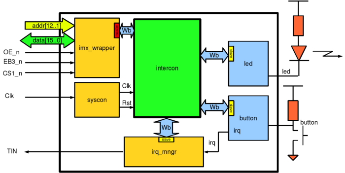
When button is pressed, the component ''button'' send interrupt signal to | When button is pressed, the component ''button'' send interrupt signal to | ||
''irq_mngr''. ''irq_mngr'' will toggle a flag and send interruption to | ''irq_mngr''. ''irq_mngr'' will toggle a flag and send interruption to | ||
'''i.MX''' processor. A Linux driver on '''i.MX''' will read ''irq_mngr'' and | '''i.MX''' processor. A Linux driver on '''i.MX''' will read ''irq_mngr'' and | ||
| − | acknowledge irq by writing '1' on | + | acknowledge irq by writing '1' on the corresponding register. And finally, Linux driver will |
| − | toggle LED value by writing | + | toggle LED value by writing in ''led'' register. |
| − | [[image:Wb_buttonled_top.png|700px|center|thumb|'''figure 1''' - ''Schematics of wishbone example'']] | + | [[image:Wb_buttonled_top.png|700px|center|thumb|'''figure 1''' - ''Schematics of wishbone example. /!\ Bus signals are wrong for the APF51 because addr and data are multiplexed.'']] |
''imx_wrapper'', ''syscon'' and ''irq_mngr'' are standards | ''imx_wrapper'', ''syscon'' and ''irq_mngr'' are standards | ||
| Line 27: | Line 26: | ||
=== Wrapper === | === Wrapper === | ||
| − | The [http://armadeus. | + | The [http://armadeus.git.sourceforge.net/git/gitweb.cgi?p=armadeus/armadeus;a=blob;f=firmware/wishbone_example/src/wishbone_wrapper.vhd;h=d23110bac06cb121677e551c9eb5efc36b9e5981;hb=HEAD wrapper] is used to convert i.MX interface signals into Wishbone signals. |
| − | + | ||
| − | + | ||
| − | + | ||
| − | + | ||
| − | + | ||
| − | + | ||
| − | + | ||
| − | + | ||
| − | + | ||
| − | + | ||
| − | + | ||
| − | + | ||
| − | + | ||
| − | + | ||
| − | + | ||
| − | + | ||
| − | + | ||
| − | + | ||
| − | + | ||
| − | + | ||
| − | + | ||
| − | + | ||
| − | + | ||
| − | + | ||
| − | + | ||
| − | + | ||
| − | + | ||
| − | + | ||
| − | + | ||
| − | + | ||
| − | + | ||
=== Intercon === | === Intercon === | ||
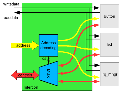
| − | The [http://armadeus. | + | The [http://armadeus.git.sourceforge.net/git/gitweb.cgi?p=armadeus/armadeus;a=blob;f=firmware/wishbone_example/src/intercon.vhd;h=dfa98f69ee2263a715945173e138c846e186981c;hb=HEAD intercon] is a component used to manage signals between Wishbone master and slave components. This component decode Wishbone-master addresses and dispatch them to Wishbone-slave components. |
[[image:Wb_intercon.png|center|500px|thumb|'''figure 2''' - ''Intercon internal structure'']] | [[image:Wb_intercon.png|center|500px|thumb|'''figure 2''' - ''Intercon internal structure'']] | ||
| Line 72: | Line 40: | ||
=== irq manager === | === irq manager === | ||
| − | Some components (here, only ''button'') generate interrupts, [http://armadeus. | + | Some components (here, only ''button'') generate interrupts, [http://armadeus.git.sourceforge.net/git/gitweb.cgi?p=armadeus/armadeus;a=blob;f=firmware/wishbone_example/src/irq_mngr.vhd;h=014735fb81478b668091beac08af358d6c61240c;hb=HEAD irq manager] is used to mux these interrupts for i.MX. The irq_mngr can manage up to 16 internal interrupts. |
IRQ manager component has tree registers, one to enable interrupts, one for flags/acknowledge interrupts and one identification register : | IRQ manager component has tree registers, one to enable interrupts, one for flags/acknowledge interrupts and one identification register : | ||
| Line 89: | Line 57: | ||
| identification register | | identification register | ||
|} | |} | ||
| − | |||
=== wb_led === | === wb_led === | ||
| − | {{Note| On apf9328_devfull and on apf27_dev a LED is already soldered on fpga. <br> '''For apf27_dev the FPGA bank1 must be powered with 3.3V''' (connect pin 39 and pin 1 on J20 header (near Ethernet one))}} | + | {{Note| On apf9328_devfull and on apf27_dev a LED is already soldered on fpga. <br> '''For apf27_dev the FPGA bank1 must be powered with 3.3V''' (connect pin 39 and pin 1 on J20 header (near Ethernet one)). For '''apf51Dev''' don't forget to power banks with jumper FPGA_Bank3 and FPGA_Bank1}} |
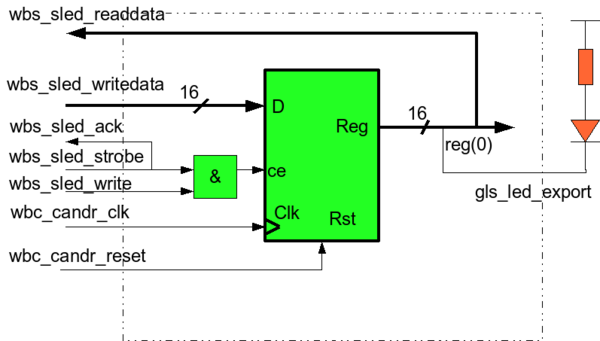
| − | This component is a simple 16-bit Wishbone slave output port, from [http:// | + | This component is a simple 16-bit Wishbone slave output port, from [http://cdn.opencores.org/downloads/wbspec_b3.pdf wishbone specification example] (p110). |
[[image:wbs_led.png|center|thumb|600px|'''figure 3''' - ''LED internal structure'']] | [[image:wbs_led.png|center|thumb|600px|'''figure 3''' - ''LED internal structure'']] | ||
| Line 105: | Line 72: | ||
{| align="center" border="1" cellpadding="5" cellspacing="0" summary="wb_led registers" | {| align="center" border="1" cellpadding="5" cellspacing="0" summary="wb_led registers" | ||
|- style="background:#efefef;" align="center" | |- style="background:#efefef;" align="center" | ||
| − | ! register !! function | + | ! register name !! (relative) address !! function |
|- | |- | ||
| − | | LED || Write '1' in LSB to shutdown LED | + | | LED || 0x00 || Write '1' in LSB to shutdown LED |
|- | |- | ||
| − | | id || read identification number | + | | id || 0x02 || read identification number |
|} | |} | ||
| Line 116: | Line 83: | ||
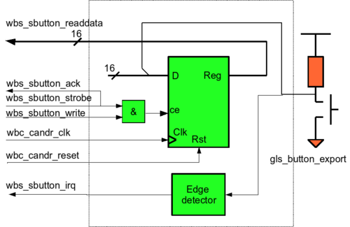
Wb_button component, is like ''led'' but in read only and with an edge detector to rise irq. | Wb_button component, is like ''led'' but in read only and with an edge detector to rise irq. | ||
| + | {{Note| On [[APF27Dev]] and [[APF51Dev]] a button is already soldered to a FPGA pin. Just don't forget to power corresponding FPGA bank.<br> For [[APF9328DevFull]] a button must be connected to IO_L01N_0 FPGA pin (connector X7/FPGA2, pin 1)}} | ||
[[image:wbs_button.png|center|thumb|500px|'''figure 4''' - ''Button internal structure'']] | [[image:wbs_button.png|center|thumb|500px|'''figure 4''' - ''Button internal structure'']] | ||
| Line 122: | Line 90: | ||
{| align="center" border="1" cellpadding="5" cellspacing="0" summary="wb_button registers" | {| align="center" border="1" cellpadding="5" cellspacing="0" summary="wb_button registers" | ||
|- style="background:#efefef;" align="center" | |- style="background:#efefef;" align="center" | ||
| − | ! register !! function | + | ! register !! (relative) address !! function |
|- | |- | ||
| − | | | + | | id || 0x00 || read identification number |
|- | |- | ||
| − | | | + | | Button || 0x02 || read LSB to know button state |
|} | |} | ||
| Line 145: | Line 113: | ||
The driver is composed of two modules : | The driver is composed of two modules : | ||
| − | * | + | * '''led_ocore''' : this module implement generic LED driver mechanisms. |
| − | * | + | * '''wb_example_led''' : This module describe specific datas for each LED-component available in design. These datas are described in structure ''plat_led_port'' and ''plat_led_device''. The module will register each LED with ''platform_device_register()'' function. When a ''plat_led_port'' device is registered, ''led_ocore'' driver will detect it and will probe it with ''led_probe'' function. |
=== button === | === button === | ||
| Line 154: | Line 122: | ||
Structure of button driver is similar to LED driver (two modules) : | Structure of button driver is similar to LED driver (two modules) : | ||
| − | * | + | * '''button_ocore''' : This module implements generic button driver mechanisms. |
| − | * | + | * '''wb_example_button''' : Like LED module, this module describes specific data for each button-component available in design. |
== Using the design == | == Using the design == | ||
| Line 164: | Line 132: | ||
ISE Webpack is mandatory to generate the bitstream, so [[ISE_WebPack_installation_on_Linux | its installation is required]]. Once bitstream has been generated, it can be downloaded in FPGA with [[Target_Software_Installation#FPGA_firmware_installation | U-Boot]] or [[FPGA_loader | Linux]]. | ISE Webpack is mandatory to generate the bitstream, so [[ISE_WebPack_installation_on_Linux | its installation is required]]. Once bitstream has been generated, it can be downloaded in FPGA with [[Target_Software_Installation#FPGA_firmware_installation | U-Boot]] or [[FPGA_loader | Linux]]. | ||
| + | For '''apf51''', bitstream is under the directory '''firmware/wishbone_example/wishbone_example51/binaries/top_wishbone_example51_lx9.bin'''. For apf27 and apf9328 bitstream can be found in '''firmware/wishbone_example/wishbone_example9328_27/bin/'''. | ||
=== Compile Linux drivers === | === Compile Linux drivers === | ||
| Line 169: | Line 138: | ||
To compile the drivers for this design select them in Linux menuconfig: | To compile the drivers for this design select them in Linux menuconfig: | ||
<pre class="host"> | <pre class="host"> | ||
| − | $ make | + | $ make linux-menuconfig |
</pre> | </pre> | ||
| Line 176: | Line 145: | ||
Armadeus specific drivers ---> | Armadeus specific drivers ---> | ||
FPGA Drivers ---> | FPGA Drivers ---> | ||
| − | [*] | + | [*] Board designs |
| − | <M> | + | [*] board drivers for wishbone example |
| − | <M> | + | <M> board Button |
| − | <M> | + | <M> board Led |
| + | <M> board irq | ||
</pre> | </pre> | ||
and compile them: | and compile them: | ||
<pre class="host"> | <pre class="host"> | ||
| − | $ make | + | $ make linux && make |
</pre> | </pre> | ||
| Line 198: | Line 168: | ||
<pre class="apf"> | <pre class="apf"> | ||
# modprobe irq_ocore | # modprobe irq_ocore | ||
| + | # modprobe wb_example_irq_mngr | ||
</pre> | </pre> | ||
* Button generic module must be loaded before board module: | * Button generic module must be loaded before board module: | ||
<pre class="apf"> | <pre class="apf"> | ||
| − | # modprobe | + | # modprobe button_ocore |
| − | # modprobe | + | # modprobe wb_example_buttons |
| − | BUTTON0: MAJOR: | + | button button.0: BUTTON0: MAJOR: 249 MINOR: 0 |
| − | + | BUTTON0 loaded | |
| − | BUTTON0 | + | |
</pre> | </pre> | ||
* LED generic module must be loaded before board module: | * LED generic module must be loaded before board module: | ||
<pre class="apf"> | <pre class="apf"> | ||
| − | # modprobe | + | # modprobe led_ocore |
| − | # modprobe | + | # modprobe wb_example_led |
| − | LED0: MAJOR: | + | LED0: MAJOR: 248 MINOR: 0 |
LED module LED0 insered | LED module LED0 insered | ||
</pre> | </pre> | ||
| Line 217: | Line 187: | ||
==== Device access ==== | ==== Device access ==== | ||
| − | Devices access are done with special caracters file. These file must be created with major and minor number given when modules are loaded (see ''Load modules'' above) : | + | Devices access are done with special caracters file. These file must be created '''with major and minor number given when modules are loaded''' (see ''Load modules'' above) : |
* Make LED access : | * Make LED access : | ||
<pre class="apf"> | <pre class="apf"> | ||
| − | # mknod /dev/led0 c | + | # mknod /dev/led0 c LED_MAJOR_NUMBER 0 |
</pre> | </pre> | ||
* Make button access : | * Make button access : | ||
<pre class="apf"> | <pre class="apf"> | ||
| − | # mknod /dev/button0 c | + | # mknod /dev/button0 c BUTTON_MAJOR_NUMBER 0 |
</pre> | </pre> | ||
| + | |||
| + | Replace '''LED_MAJOR_NUMBER''' and '''BUTTON_MAJOR_NUMBER''' with correct major number given when modprobe is done. | ||
==== Test LED ==== | ==== Test LED ==== | ||
| − | A test program is available in | + | A test program is available in module directory: |
| + | <pre class="host"> | ||
| + | target/linux/modules/fpga/board_designs/wishbone_example/wb_led/ | ||
| + | </pre> | ||
| + | simply compile it with arm-linux-gcc compiler : | ||
<pre class="host"> | <pre class="host"> | ||
| − | $ | + | $ make test |
</pre> | </pre> | ||
| − | Download | + | Download ''testled'' binary on your APF, then test it : |
<pre class="apf"> | <pre class="apf"> | ||
# ./testled /dev/led0 | # ./testled /dev/led0 | ||
| Line 253: | Line 229: | ||
==== Test Button ==== | ==== Test Button ==== | ||
| − | A test program is available in | + | A test program is available in directory: |
| − | + | ||
<pre class="host"> | <pre class="host"> | ||
| − | + | target/linux/modules/fpga/board_designs/wishbone_example/wb_button/ | |
| + | </pre> | ||
| + | simply compile it in the directory with command: | ||
| + | <pre class="host"> | ||
| + | $ make test | ||
</pre> | </pre> | ||
| + | copy the ''testbutton'' binary in your target then launch it: | ||
<pre class="apf"> | <pre class="apf"> | ||
# ./testbutton /dev/button0 | # ./testbutton /dev/button0 | ||
| Line 274: | Line 254: | ||
</pre> | </pre> | ||
| − | Each time button is pushed or released, | + | Each time button is pushed or released, button state is printed out. |
==== Switching LED with button ==== | ==== Switching LED with button ==== | ||
| − | A simple program is available in | + | A simple program is available in wishbone example directory: |
| + | <pre class="host"> | ||
| + | target/linux/modules/fpga/board_designs/wishbone_example/ | ||
| + | </pre> | ||
| + | to switch on the LED when button is pressed. | ||
To compile : | To compile : | ||
<pre class="host"> | <pre class="host"> | ||
| − | + | $ make test | |
</pre> | </pre> | ||
| − | To use it, simply type : | + | To use it, simply type (after downloaded it under your target): |
<pre class="apf"> | <pre class="apf"> | ||
Latest revision as of 12:43, 30 June 2022
This article is intended to explain how to design Wishbone compatible components with simple example.
The VHDL source code can be found in firmware/wishbone_example from our gitlab repository.
Description of the Wishbone structure for Armadeus APF boards can be found here (in french).
Contents
General structure
The main functionality of this component is to allow to switch-on a LED when a button is pressed.
When button is pressed, the component button send interrupt signal to irq_mngr. irq_mngr will toggle a flag and send interruption to i.MX processor. A Linux driver on i.MX will read irq_mngr and acknowledge irq by writing '1' on the corresponding register. And finally, Linux driver will toggle LED value by writing in led register.
imx_wrapper, syscon and irq_mngr are standards ARMadeus-Wishbone IPs that just been instantiated in our design.
button and led are simple slave component we want to integrate in the FPGA.
All these components are connected together with the 'glue logic' component intercon.
Wrapper
The wrapper is used to convert i.MX interface signals into Wishbone signals.
Intercon
The intercon is a component used to manage signals between Wishbone master and slave components. This component decode Wishbone-master addresses and dispatch them to Wishbone-slave components.
Wishbone slave application components
In this example there are 3 Wishbone-slave components :
irq manager
Some components (here, only button) generate interrupts, irq manager is used to mux these interrupts for i.MX. The irq_mngr can manage up to 16 internal interrupts.
IRQ manager component has tree registers, one to enable interrupts, one for flags/acknowledge interrupts and one identification register :
| register | function |
|---|---|
| mask | write '1' to allow irq |
| ack/pend | read for pending irq, write to acknowledge irq |
| id | identification register |
wb_led
This component is a simple 16-bit Wishbone slave output port, from wishbone specification example (p110).
It is a simple register, that can be read and write. The LED is controlled with register pin 0.
The two registers are :
| register name | (relative) address | function |
|---|---|---|
| LED | 0x00 | Write '1' in LSB to shutdown LED |
| id | 0x02 | read identification number |
wb_button
Wb_button component, is like led but in read only and with an edge detector to rise irq.
| |
Note: On APF27Dev and APF51Dev a button is already soldered to a FPGA pin. Just don't forget to power corresponding FPGA bank. For APF9328DevFull a button must be connected to IO_L01N_0 FPGA pin (connector X7/FPGA2, pin 1) |
The two registers are:
| register | (relative) address | function |
|---|---|---|
| id | 0x00 | read identification number |
| Button | 0x02 | read LSB to know button state |
Components drivers
Each component is driven by a Linux driver described above. All driver code is in armadeus directory in target/linux/module/fpga/wishbone_example/.
Each component has an identification register with unique number. This number is used by driver when modprobed to unsure that device is present.
irq manager
The description of IRQ management module is available here. The module's source code can be found here.
LED
LED driver is seen in Linux like a character driver. Writing in a /dev file will enable or disable the LED.
The driver is composed of two modules :
- led_ocore : this module implement generic LED driver mechanisms.
- wb_example_led : This module describe specific datas for each LED-component available in design. These datas are described in structure plat_led_port and plat_led_device. The module will register each LED with platform_device_register() function. When a plat_led_port device is registered, led_ocore driver will detect it and will probe it with led_probe function.
button
Button driver is seen in Linux like a character driver. When a process want to read value in button register, the driver will block reading until an interrupt occur.
Structure of button driver is similar to LED driver (two modules) :
- button_ocore : This module implements generic button driver mechanisms.
- wb_example_button : Like LED module, this module describes specific data for each button-component available in design.
Using the design
All code for this design is available in ARMadeus tree, firmware (VHDL) and software (Linux drivers).
Make the FPGA bitstream
ISE Webpack is mandatory to generate the bitstream, so its installation is required. Once bitstream has been generated, it can be downloaded in FPGA with U-Boot or Linux. For apf51, bitstream is under the directory firmware/wishbone_example/wishbone_example51/binaries/top_wishbone_example51_lx9.bin. For apf27 and apf9328 bitstream can be found in firmware/wishbone_example/wishbone_example9328_27/bin/.
Compile Linux drivers
To compile the drivers for this design select them in Linux menuconfig:
$ make linux-menuconfig
    Device Drivers --->
        Armadeus specific drivers --->
            FPGA Drivers --->
                [*]   Board designs
                [*]     board drivers for wishbone example
                <M>       board Button
                <M>       board Led
                <M>       board irq
and compile them:
$ make linux && make
Then reflash Linux and rootfs images.
Play with button and LED
Load modules
Modules must be loaded in right order with modprobe command :
- IRQ manager :
# modprobe irq_ocore
# modprobe wb_example_irq_mngr
- Button generic module must be loaded before board module:
# modprobe button_ocore
# modprobe wb_example_buttons
button button.0: BUTTON0: MAJOR: 249 MINOR: 0
BUTTON0 loaded
- LED generic module must be loaded before board module:
# modprobe led_ocore
# modprobe wb_example_led
LED0: MAJOR: 248 MINOR: 0
LED module LED0 insered
Device access
Devices access are done with special caracters file. These file must be created with major and minor number given when modules are loaded (see Load modules above) :
- Make LED access :
# mknod /dev/led0 c LED_MAJOR_NUMBER 0
- Make button access :
# mknod /dev/button0 c BUTTON_MAJOR_NUMBER 0
Replace LED_MAJOR_NUMBER and BUTTON_MAJOR_NUMBER with correct major number given when modprobe is done.
Test LED
A test program is available in module directory:
target/linux/modules/fpga/board_designs/wishbone_example/wb_led/
simply compile it with arm-linux-gcc compiler :
$ make test
Download testled binary on your APF, then test it :
# ./testled /dev/led0
Testing led driver
Read 1
Write 0
Read 0
Write 1
Read 1
Write 0
Read 0
LED is blinking slowly.
Test Button
A test program is available in directory:
target/linux/modules/fpga/board_designs/wishbone_example/wb_button/
simply compile it in the directory with command:
$ make test
copy the testbutton binary in your target then launch it:
# ./testbutton /dev/button0
Testing button driver
Read 1
Read 0
Read 1
Read 0
Read 1
Read 0
Read 0
Read 1
Read 0
Read 1
Each time button is pushed or released, button state is printed out.
Switching LED with button
A simple program is available in wishbone example directory:
target/linux/modules/fpga/board_designs/wishbone_example/
to switch on the LED when button is pressed.
To compile :
$ make test
To use it, simply type (after downloaded it under your target):
# ./push-led /dev/button0 /dev/led0
Blink a led pushing button
Push the button to switch on/off the LED.


