Difference between revisions of "CAN bus Linux sja1000"
| Line 73: | Line 73: | ||
Please, ask ARMadeus for source code. | Please, ask ARMadeus for source code. | ||
| − | == Linux device platform source == | + | == Write a Linux device platform source == |
Actually, the driver of the SJA1000 si present in the kernel, but the module can't be probed. | Actually, the driver of the SJA1000 si present in the kernel, but the module can't be probed. | ||
You have to write your device module, the structures of this device module must be similar with the following: | You have to write your device module, the structures of this device module must be similar with the following: | ||
Revision as of 09:21, 5 May 2011
This page explain how to communicate with a CAN bus through the SJA1000 CAN controller and a TJA1040 CAN Transceiver.
| |
Warning: There is no SJA1000 CAN controller on ARMadeus boards, you have to create your own assembly. The assembly used for doing this test is given on this page. |
Contents
Hardware Requirements
- APF27-Dev and APF27 with FPGA Spartan 3A
- 8 bits transceiver 74LVXC3245 (2x)
- CAN bus controller SJA1000
- 24Mhz oscillator MXO45HST24M0000
- CAN bus transceiver TJA1040
- Resistors and capacitances
Realisation
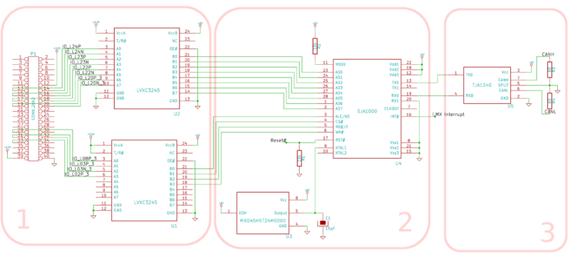
Foremost, you have to create the following assembly.
I have decomposed this assembly in three stage. For further informations, please read datasheets!
- Stage 1 - Adaptation
The purpose of this stage is to convert the FPGA's signals 3V3 in 5V signals. The transceiver 74LVXC3245 convert the bidirectionnal signals A0..A7 and the outputs ALE/AS, CS#, RD#/E and WR# from the FPGA. The connector P1 is connected to J20 on APF27-Dev.
- Stage 2 - CAN bus Controller
The CAN bus controller receives messages from the adaptation stage (1). It is clocked with a 24Mhz Oscillator MXPO45HST24M0000. The SJA1000 send/receive message on/from the bus by communication with the TJA1040 on stage 3.
| |
Note: In our case, the interruption pin of the SJA1000 (INT#) is soldered on the switch S1 on the APF27-Dev but it is possible to through the FPGA! |
- Stage 3 - Communication with CAN bus
The TJA1040 ensures the communication between the SJA1000 controller and the CAN bus. The split pin is used to stabilize the common mode and must be wired to GND.
Pinout
3V3 is supplied by pin 39 from J20 on APF27-Dev. This pin is wired to pin 1 for each 8-Bits transceivers.
Buffer U2 - address & data
| J20 - Pins | Name on APF27-Dev schematic | Functionnalities |
|---|---|---|
| 13 | IO_L24P_3 | AD0 |
| 14 | IO_L24N_3 | AD1 |
| 15 | IO_L23P_3 | AD2 |
| 16 | IO_L23N_3 | AD3 |
| 17 | IO_L22P_3 | AD4 |
| 18 | IO_L22N_3 | AD5 |
| 19 | IO_L20P_3 | AD6 |
| 20 | IO_L20N_3 | AD7 |
Buffer U1 - control
| J20 - Pins | Name on APF27-Dev schematic | Functionnalities |
|---|---|---|
| 29 | IO_L08P_3 | ALE/AS |
| 31 | IO_L03P_3 | CS# |
| 32 | IO_L03N_3 | RD#/E |
| 33 | IO_L02P_3 | WR# |
VHDL
The VHDL description is used to communicate with the assembly respecting the communication protocole of the SJA1000. Load the firmware in the FPGA of the ARMadeus Board. Please, ask ARMadeus for source code.
Write a Linux device platform source
Actually, the driver of the SJA1000 si present in the kernel, but the module can't be probed. You have to write your device module, the structures of this device module must be similar with the following:
	static struct resource sja1000_resources[] = {
	[0] = {
		.start = ARMADEUS_FPGA_BASE_ADDR + SJA1000_WISHBONE_ADDRESS_BASE,
		.end = ARMADEUS_FPGA_BASE_ADDR + SJA1000_WISHBONE_ADDRESS_BASE + 0x1ff,
		.flags = IORESOURCE_MEM | IORESOURCE_MEM_16BIT,
	},
	[1] = {
		.start = gpio_to_irq(IO_PIN_IRQ_SJA1000),
		.end     = gpio_to_irq(IO_PIN_IRQ_SJA1000),
		.flags   = IORESOURCE_IRQ | IORESOURCE_IRQ_LOWEDGE,
	},
};
static struct sja1000_platform_data sja1000_pdata = {
	.osc_freq = 24000000,
	.ocr = OCR_MODE_NORMAL | OCR_TX0_PULLDOWN | OCR_TX1_PULLDOWN,
	.cdr = CDR_PELICAN | CDR_CBP,
};
Ask ARMadeus for source code.
Usage
Load the module
  $ modprobe sja1000_platform
  $ modprobe your_sja1000_device_module
Set the bitrate and set the interface up
$ ip link set can0 up type can bitrate 1250000
And then you can use your new CAN interface with the tools used on others page about CAN bus on ARMadeus boards.
Links
datasheets
