Difference between revisions of "FPGA and led"
From ArmadeusWiki
| Line 22: | Line 22: | ||
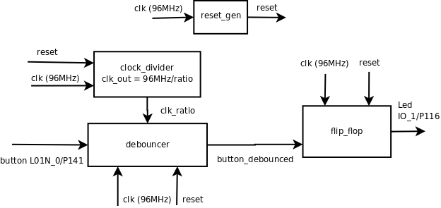
The led_top.vhd is a VHDL file where the components of the circuit are instantiated and connected between them. | The led_top.vhd is a VHDL file where the components of the circuit are instantiated and connected between them. | ||
| − | The functional diagram of the circuit is : | + | The functional diagram of the circuit is : |
[[Image:led_top.png]] | [[Image:led_top.png]] | ||
Revision as of 22:58, 14 April 2007
This project is intented for people who are new to VHDL.
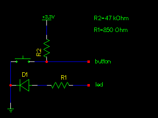
We will connect a switch and a led to the FPGA and use some VHDL code to toggle the led state each time the switch is pressed.
Some usefull informations:
The main FPGA page [[1]] of the armadeus wiki.
This document [2] gives a lot of usefull information on how to use ISE Webpack.
Page 9 of this document shows the devlight pinout matrix: [3]
Pages 28 and 29 of the APF datasheet shows the mapping of the devlight pinouts with the FPGA pinouts :[4]
Schematic
Anatomy of the circuit
The led_top.vhd is a VHDL file where the components of the circuit are instantiated and connected between them.
The functional diagram of the circuit is :
Benoît Canet / benoit on #armadeus

